
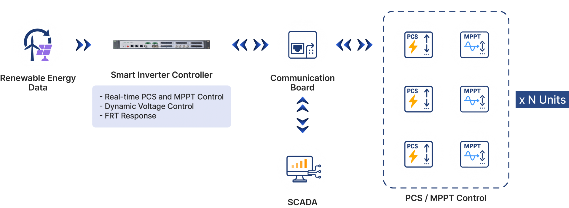
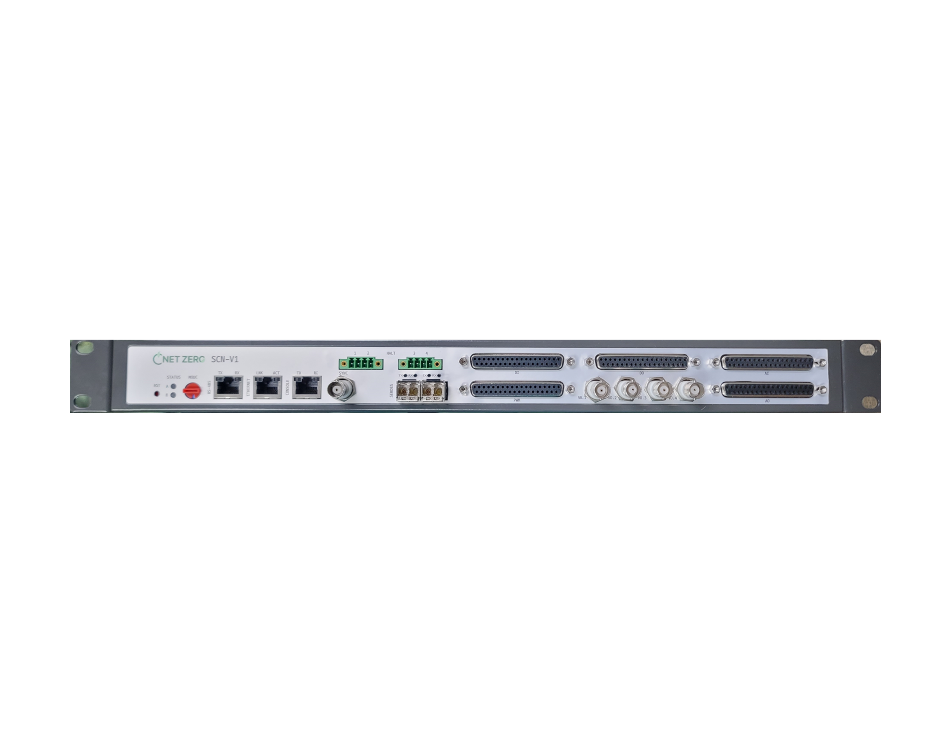
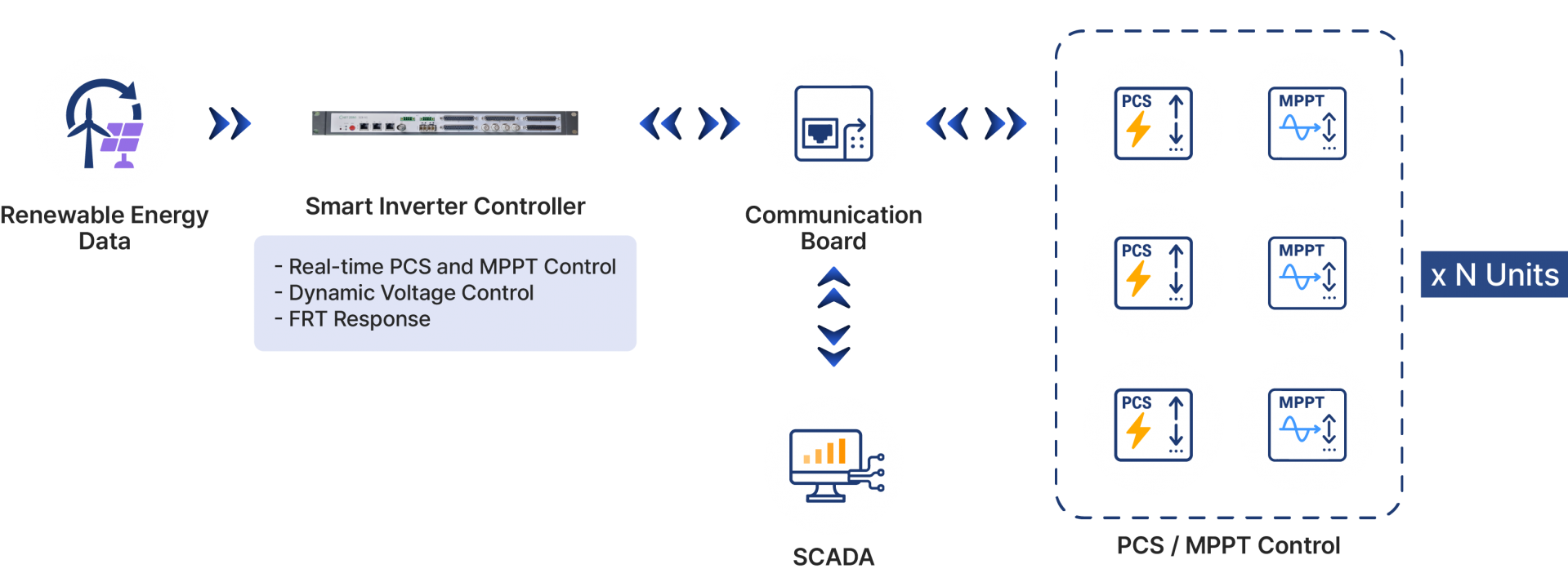
 | The smart controller utilizes renewable energy output data and frequency-tracking functions to respond to grid frequency changes in real time, while integrating distributed PCS units through a communication board. Each PCS performs MPPT independently to enhance energy conversion efficiency, enabling effective renewable energy control and stable operation when connected to the grid. This configuration serves as a carbon-neutral control infrastructure suitable for smart grid and microgrid applications. |
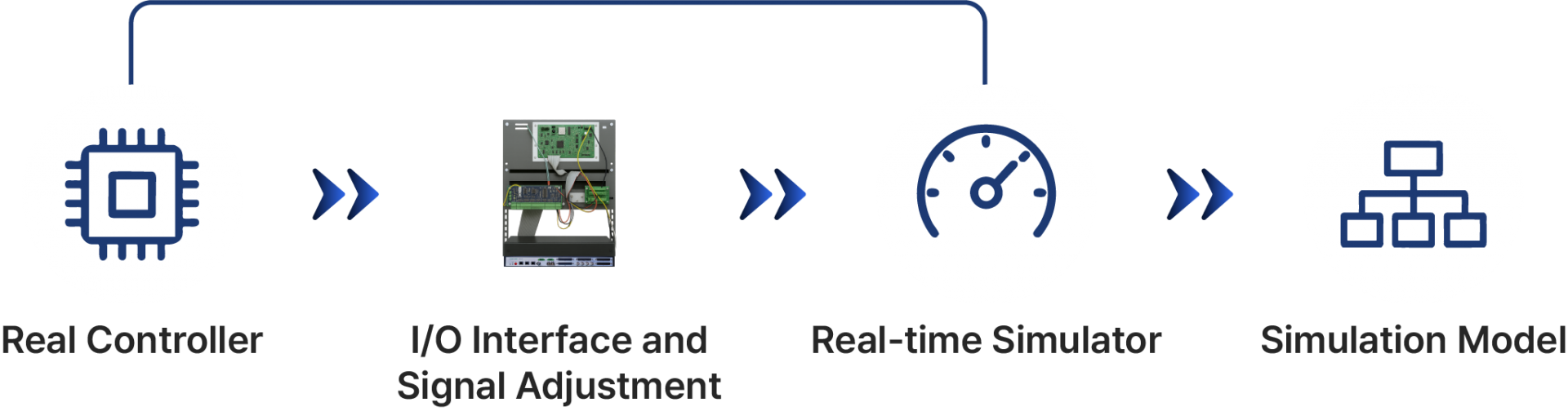
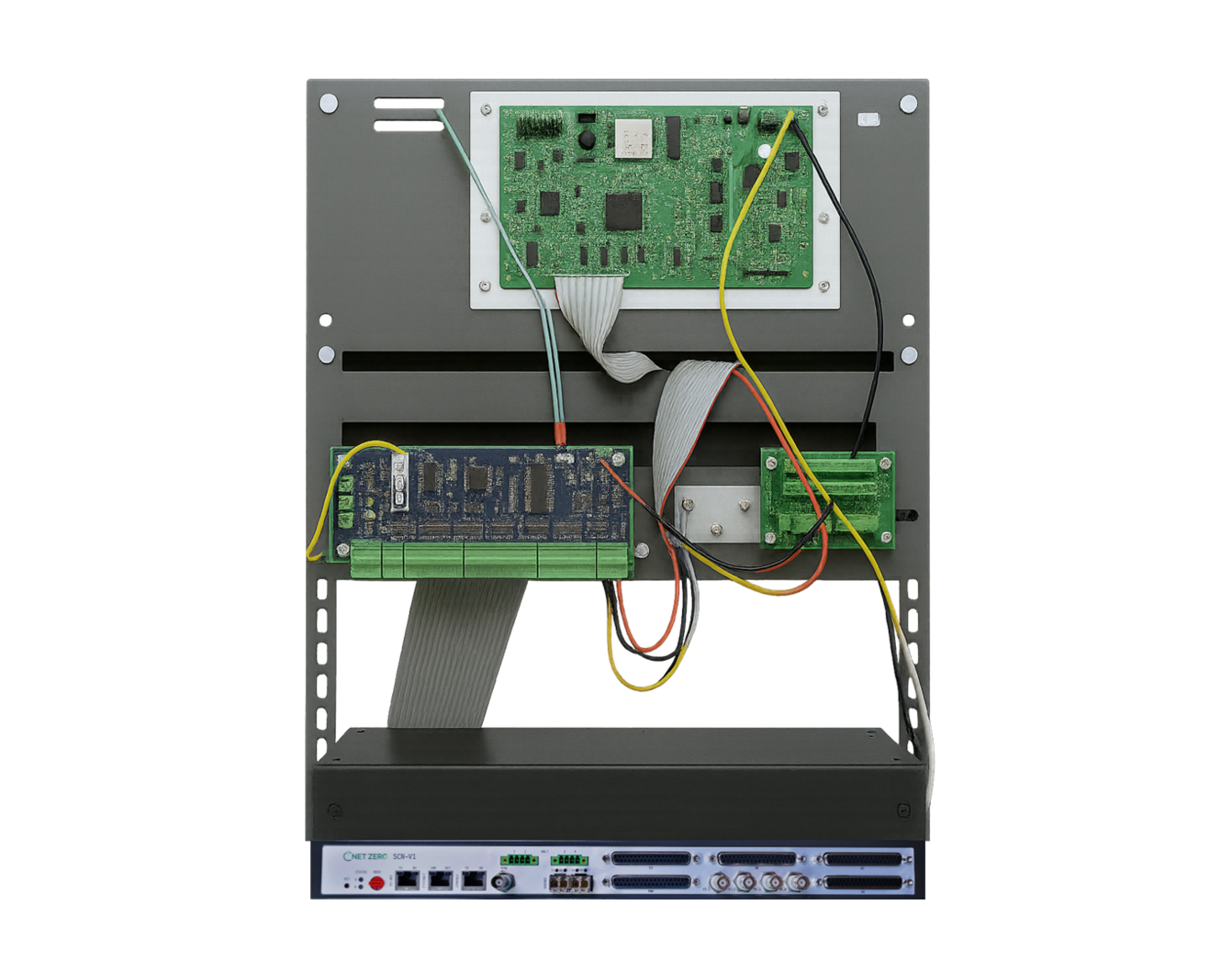
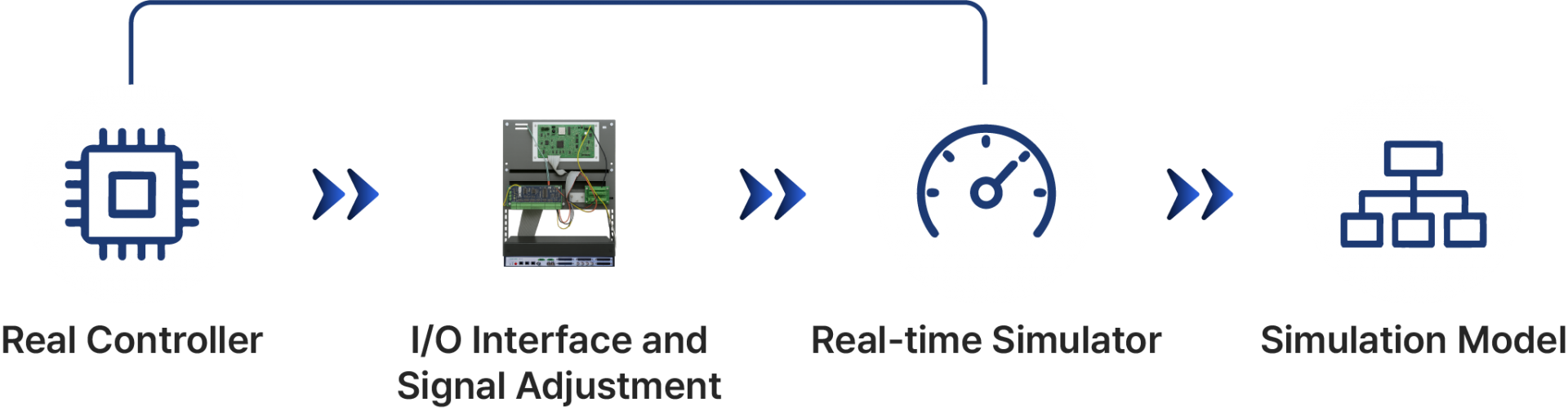
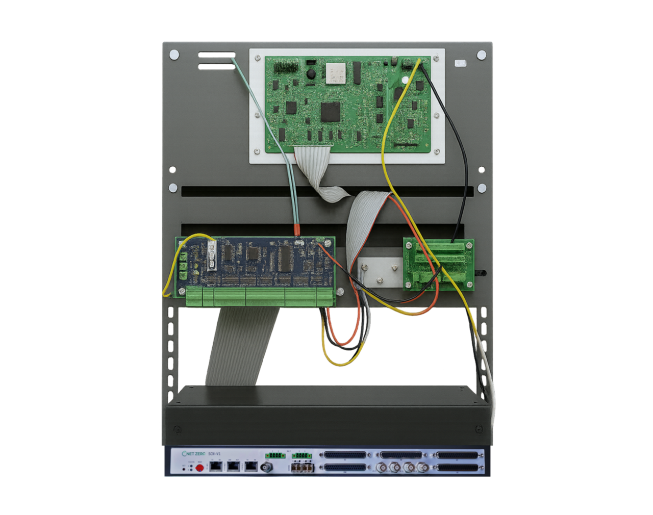
| The HILS interface refers to Hardware-In-the-Loop Simulation (HILS) — a technology that tests real hardware components within a virtual environment. It allows developers to simulate the operating conditions of actual hardware, enabling performance evaluation and error detection during the development and verification of complex systems. HILS technology simulates various environments before on-site testing, enabling thorough verification and reducing both cost and time during development. It is widely applied across multiple industries. For HILS validation, a suitable verification system can be built by integrating control devices, simulation models, RTS, and input/output interfaces. |
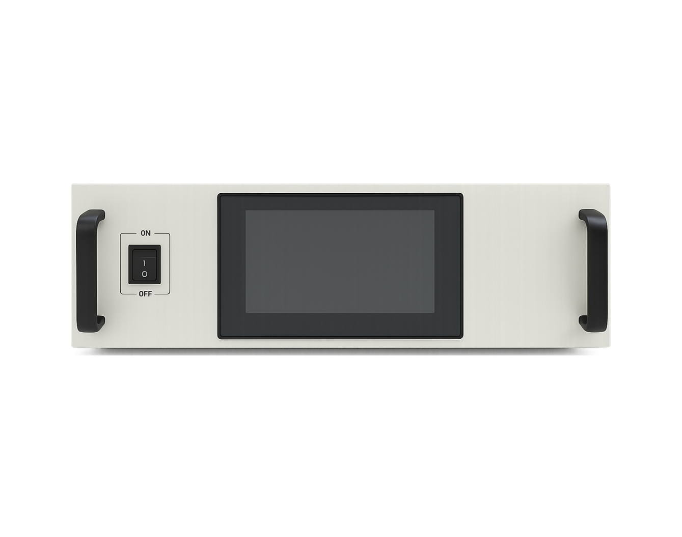
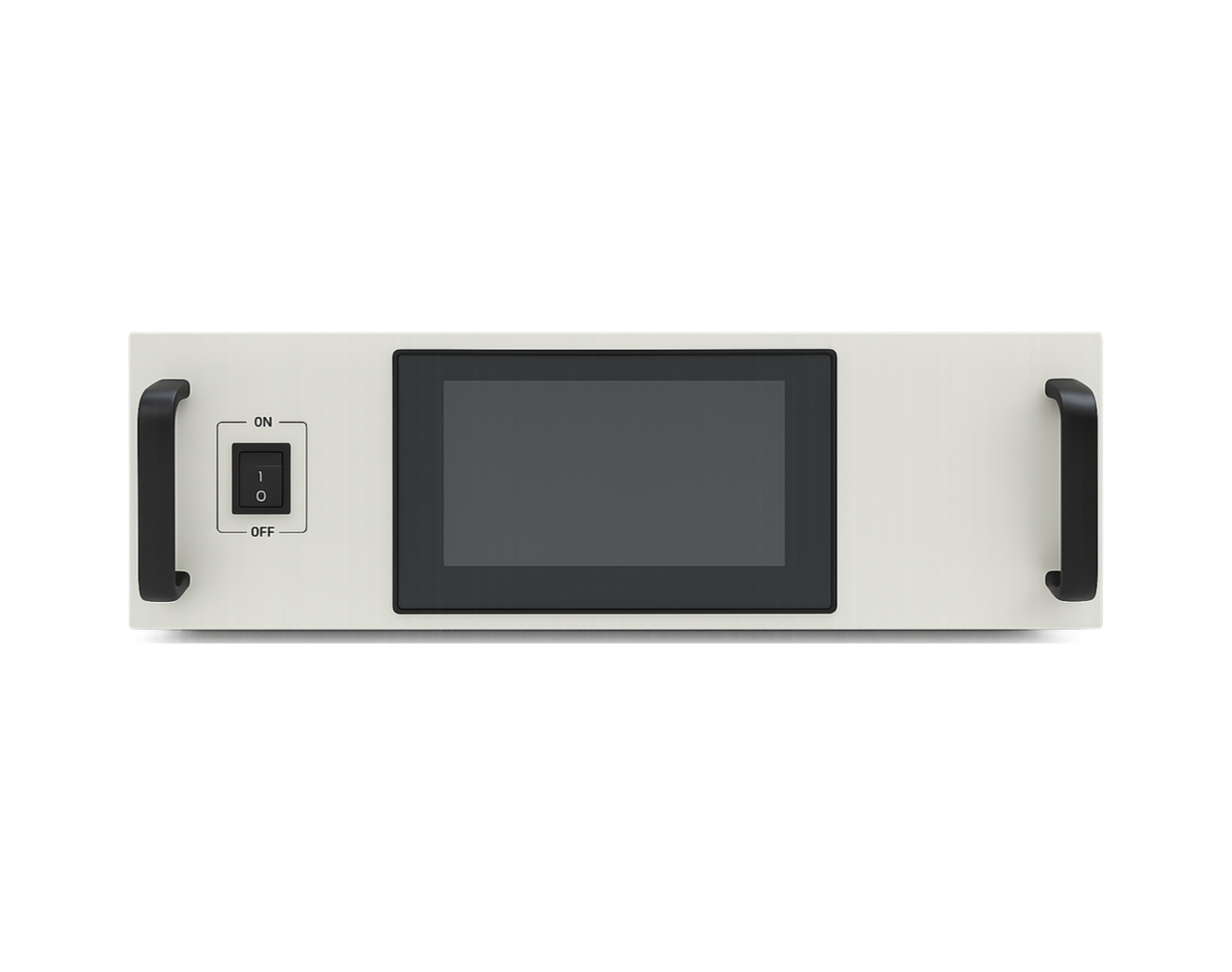
| The DC/DC converter stably converts input voltage to supply the required voltage and current to load devices. It supports remote monitoring and control through an RS485 interface based on the standard Modbus communication protocol. Designed in a 19-inch rack-mount structure, it allows easy installation and maintenance while minimizing system energy loss through high-efficiency power conversion. |
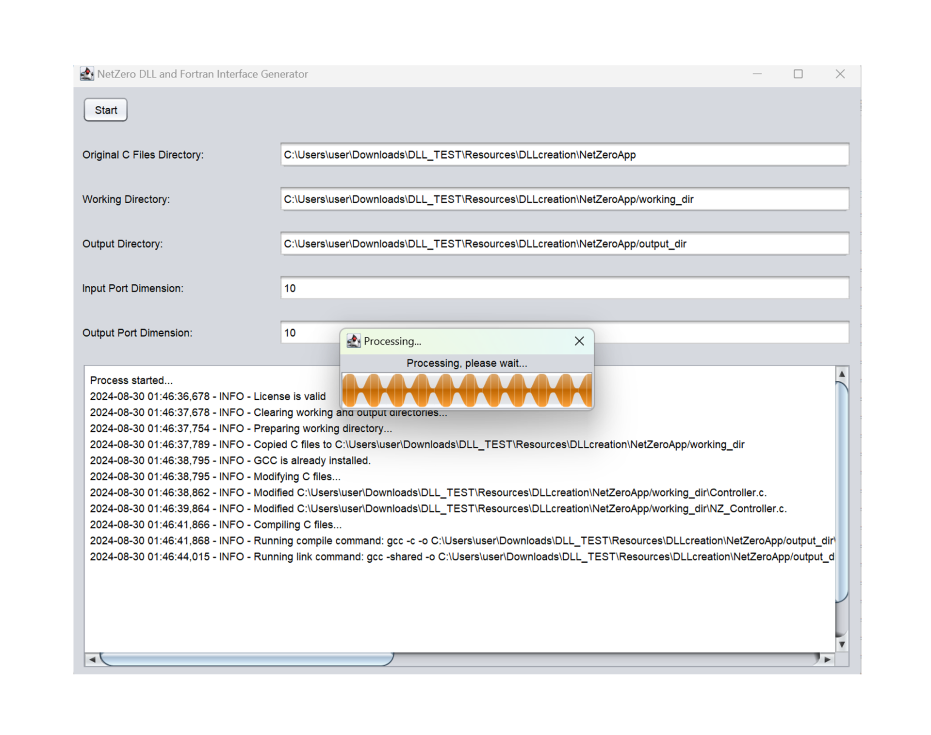
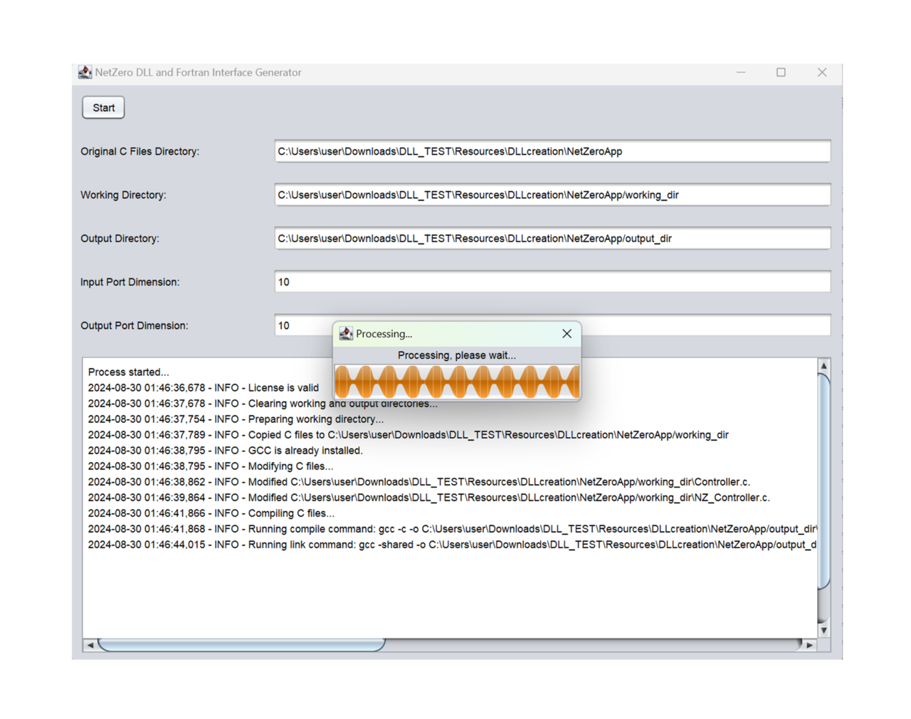
| Netzero DLL Creator (NDC V1) converts a manufacturer’s proprietary C-based control algorithm into DLL and LIB files executable directly on an EMT simulator, enabling high-precision simulations based on actual control code. Through a GUI interface, users can select input sources, configure parameters, and set test conditions, enabling automation and enhanced reliability in the modeling process. It can be applied to various EMT-based analysis environments, such as renewable energy system analysis, controller validation, and simulation optimization. |
 | The smart controller utilizes renewable energy output data and frequency-tracking functions to respond to grid frequency changes in real time, while integrating distributed PCS units through a communication board. Each PCS performs MPPT independently to enhance energy conversion efficiency, enabling effective renewable energy control and stable operation when connected to the grid. This configuration serves as a carbon-neutral control infrastructure suitable for smart grid and microgrid applications. |
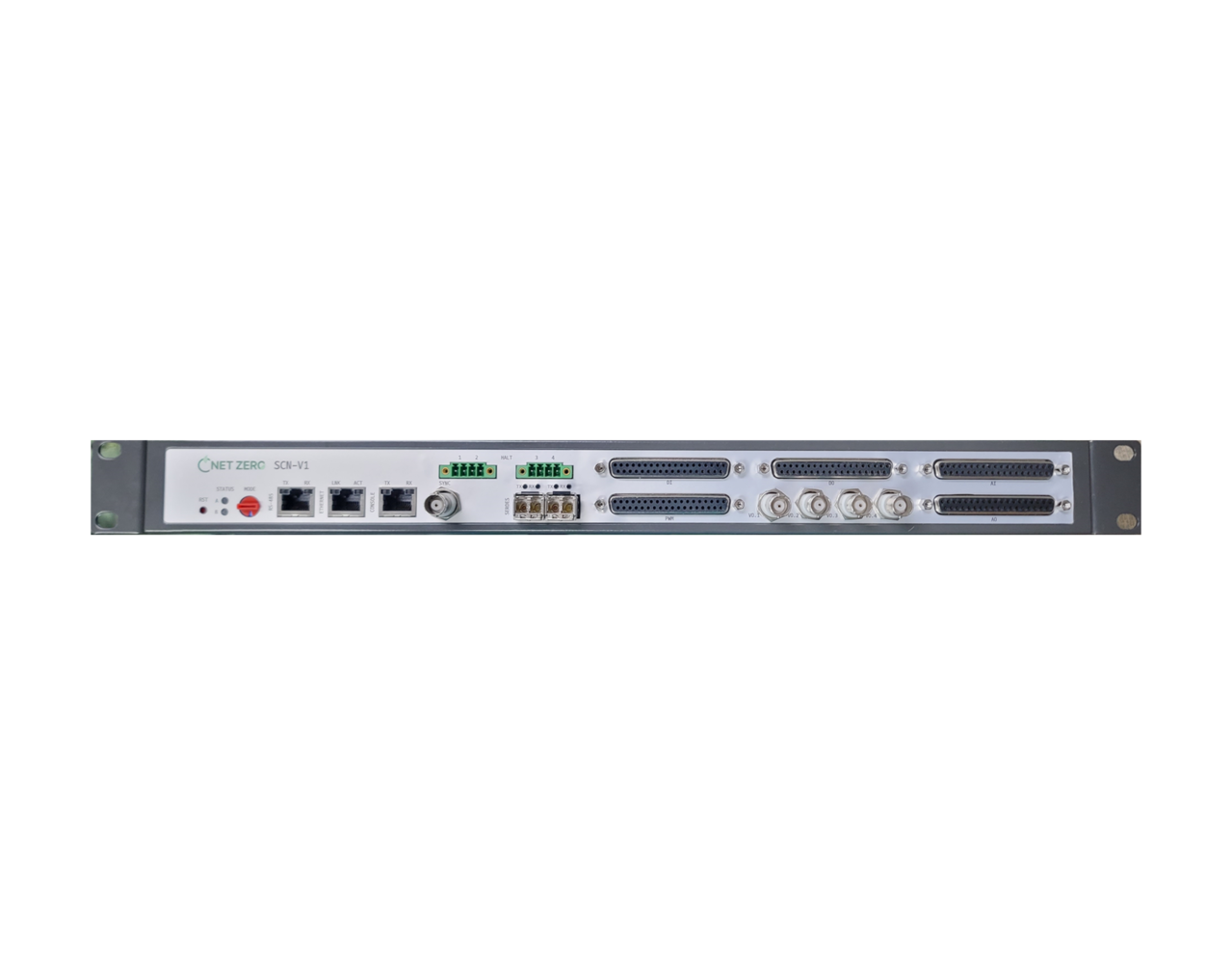
| The HILS interface refers to Hardware-In-the-Loop Simulation (HILS) — a technology that tests real hardware components within a virtual environment. It allows developers to simulate the operating conditions of actual hardware, enabling performance evaluation and error detection during the development and verification of complex systems. HILS technology simulates various environments before on-site testing, enabling thorough verification and reducing both cost and time during development. It is widely applied across multiple industries. For HILS validation, a suitable verification system can be built by integrating control devices, simulation models, RTS, and input/output interfaces. |
| The DC/DC converter stably converts input voltage to supply the required voltage and current to load devices. It supports remote monitoring and control through an RS485 interface based on the standard Modbus communication protocol. Designed in a 19-inch rack-mount structure, it allows easy installation and maintenance while minimizing system energy loss through high-efficiency power conversion. |
| Netzero DLL Creator (NDC V1) converts a manufacturer’s proprietary C-based control algorithm into DLL and LIB files executable directly on an EMT simulator, enabling high-precision simulations based on actual control code. Through a GUI interface, users can select input sources, configure parameters, and set test conditions, enabling automation and enhanced reliability in the modeling process. It can be applied to various EMT-based analysis environments, such as renewable energy system analysis, controller validation, and simulation optimization. |

Headquarters R&D Center
#506, The First Tower, 10 Dongtandaero 21-gil, Yeongcheon-dong, Hwaseong-si, Gyeonggi-do
Factory
#510, The First Tower, 10 Dongtandaero 21-gil, Yeongcheon-dong, Hwaseong-si, Gyeonggi-do
2nd R&D - Yonsei University
Room 212-A-2, Engineering Hall, Yonsei University, 50 Yonsei-ro, Seodaemun-gu, Seoul
3rd R&D - KAIST Mobility Center
Room 207(208), 2F, 6 Cheomdansandan 5-gil, Hongbuk-eup, Hongseong-gun, Chungcheongnam-do
 | ||
Headquarters R&D Center #506, The First Tower, 10 Dongtandaero 21-gil, Yeongcheon-dong, Hwaseong-si, Gyeonggi-do Factory #510, The First Tower, 10 Dongtandaero 21-gil, Yeongcheon-dong, Hwaseong-si, Gyeonggi-do | 2nd R&D - Yonsei University Room 212-A-2, Engineering Hall, Yonsei University, 50 Yonsei-ro, Seodaemun-gu, Seoul 3rd R&D - KAIST Mobility Center Room 207(208), 2F, 6 Cheomdansandan 5-gil, Hongbuk-eup, Hongseong-gun, Chungcheongnam-do |